|

Optional
PLC I/O Library
 |
 |
 |
|
|
|
|
|
Constructor
16
/ PLC I/O
Library
Combo
CM-100-16-Plus
$798.00
$689.00 |
|
|
|
|
|
 |
|
 |
|
|
Note:
To qualify for
Upgrade versions below you must
the Product Serial Number from the
Constructor version you own (v12- v15), and the name
it is registered to.

|
|
|
|
|
|
|
|
|
Constructor
16
Upgrade from v15
CM-100-16-UPG1
$199.00 |
|
|
|
|
|
|
|
|
|
|
|
|
|
|
|
|
|
|
|
|
Constructor
16
Upgrade from v14
CM-100-16-UPG2
$249.00 |
|
|
|
|
|
|
|
|
|
|
|
for Site License Upgrade Pricing. (Include
your current version Number)
Click photos below
for a Full Screen
Picture
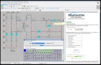
Picture of The Constructor
in the EDIT mode.
Picture of The Constructor in the
RUN
mode. Screen also shows an open
Workbook.
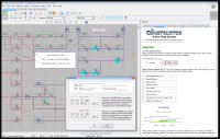
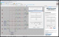
Picture of The Constructor with Open Time Delay Dialog
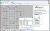
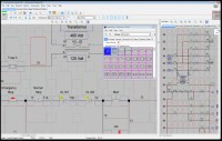
Picture of The Constructor
with PLC I/O and a load PLC I/O module
dialog box.
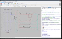
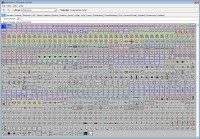
Picture of The Constructor
with wire generator screen.
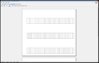
Picture of The Constructor
with wire label screen open. It shows
wire numbers applied to a Brady label template.

The Constructor
(PDF)
Export Preview Screen
The Constructor Zoom Screen |
E93839 Motherboard Schematic

Electrical
Ladder Diagram, Schematic and PLC Training / Simulation Software
for Windows 11, 10, 8, 7
The Constructor
program makes the creation, testing, trouble-shooting, teaching and
printing of electrical ladder diagrams, schematics and one line diagrams
fast and easy.
Software will be Downloadable. A
short time after Purchase, an Email will be sent with Download Link and
License Key
The Constructor
Software is unique in it's ability to test an electrical circuit.
Now the
complete circuit can be tested from the three phase power components to
the control circuit. See and Hear the circuit running. The
built-in symbol libraries of over 720 symbols makes the creation of your
diagrams fast and easy.
We also have
optional libraries containing
over 1800 Allen Bradley, Automation Direct, Cutler Hammer, GE
Fanuc, Idec, Mitsubishi, Modicon, Omron, Siemens, Telemecanique
and Toshiba PLC I/O diagrams. -
more
Create, Test and
Print Ladder Diagrams
The Constructor program makes the
creation, testing, trouble-shooting, teaching and printing of electrical
ladder diagrams, diagram schematics and one line diagrams fast and easy.
The circuit will perform the same as a hard wired electrical circuit.
The design can be edited and re-tested saving valuable time when it
comes to hard wired circuits and trouble-shooting scenarios. This
program is unique in its ability to test an electrical circuit. You can
see the power flow in the
diagram and hear the sound effects
when a motor or siren is energized. Once designed, any circuit can then
be virtually energized and
operated on your computer monitor.
The circuit simulator is a great teaching
tool. Our customers tell us the Constructor is the quickest and easiest
electrical cad software they've ever used.
Symbol Libraries
and Symbol Editor
The built-in symbol libraries of over 800
symbols makes the creation of your diagrams fast and easy. The built-in
symbol editor allows you to create your own custom electrical symbols
for that special project. Optional
PLC I/O libraries are
available for most PLCs (Over 1800 I/O modules) An optional additional
sound library allows you to add 126 more sound effects to your circuit
diagrams.
Easy to Learn and
Use
Our new Active help system, help
files, and a pdf manual makes learning to use this powerful software
much faster and easier. Your complete
circuit can be tested, from the three phase power
components to the control circuit.
Many of our customers have used
electrical cad software before and comment about how easy our software
is to use compared with other electrical cad software.
All the Features
You Need
Powerful zooming features for
faster editing and easier viewing of your electrical diagrams. Over 50
color schemes allow you to set your personal color preference. Automatic
legends and borders allow you to make
professional looking electrical diagrams quickly. You
can print your ladder diagrams out on your choice of any printer or
plotter that Windows supports.
The diagram may be saved to your
hard drive, flashdrive or a floppy disk for easy reference or
modification. You can also save images from within The Constructor
program as bitmap files.
The bitmap files can then be used
for printing or imported into other programs.
Portability
If you need to send a diagram to an
associate now you can export your diagram as a PDF
file. Exporting your diagram as a
DXF, DWG, JPG, GIF, TIF or PNG file
is also an option. Print wire labels using
pre-designed wire label templates for Brady and other label
manufacturers. Our auto wire feature allows you to quickly add wire
numbers to your diagrams with a host of options available.
Optional Additions Available
Optional
PLC I/O libraries are
available for most PLCs (Over 1800 I/O modules). An optional additional
sound library allows you to add 126 more sound effects to your circuit
diagrams.
CONSTRUCTOR
16
with Ladder Logic Simulation
NEW Features
- Improved PDF and DXF Export
- Improved installation for Windows 11.
- More Symbols - now over 900 symbols
- Enhanced/Faster method of doing assignments,
groups and associations in your diagram.
- Enhanced/Faster method of drawing wires in
your diagram.
- The probe now automatically changes from
continuity to power mode when either probe becomes in contact with
power
- Automatic creation of PDF export symbols.
- Virtually Energize and Operate Your Diagram
- Works with Windows 7, 8 10 or 11.
- Export features: PDF and DXF.
- Change Wire Colors and Styles
- Built-in Symbol Editor
- Troubleshooting Mode for Training
- Voltage/Continuity Test Probe
- Built-in Symbol Libraries of over 900 JIC,
NEMA and IEC Symbols
- Symbol Library Search
- Sound Effects (Hear the Difference!)
- Interactive on-screen help
- Easier and faster to use than most CAD
Software
- Generic PLC I/O modules and Terminal Strip
libraries
- Automatic Wire Numbering and Re-numbering
- Auto High-Lighting of Contacts Assigned to
Coils
- Simulation Scripting - Run your circuit hands
free
E93839 Motherboard Schematic
To find the diagram on electronics repair sites (like Elektrotanya, Vinafix, or Badcaps), use these search queries:
The "Boardview" File:
If you are doing repairs (tracing power rails, finding short circuits), you often need the Boardview file (.brd or .bdv) alongside the schematic. Boardview shows the physical layout and component coordinates, whereas the schematic shows the electrical logic.
A Deep Dive into the Dell OptiPlex Mainboard Architecture
The motherboard labeled with the Foxconn code E93839 is a staple in the enterprise computing world, most commonly recognized as the system board for the Dell OptiPlex 790 (and electrically similar to the 780). For hardware technicians and electronics repair engineers, understanding the schematic of this board is essential for diagnosing power failures, BIOS corruption, and peripheral issues.
This article breaks down the critical sections of the E93839 schematic design. E93839 Motherboard Schematic
Advanced users use schematics to find UART or JTAG headers. Flashing new firmware onto the bridge controller can sometimes unlock drives that are stuck in a "busy" state. The E93839 schematic reveals:
The most critical aspect of the schematic for repair technicians is the power sequence. If this sequence breaks, the board will exhibit "No POST" or "No Power" symptoms. The sequence is managed by the System Management Controller (SMC) or Embedded Controller.
Typical Power-On Sequence:
-
Memory subsystem
-
Platform Controller/Chipset (PCH) and PMIC
-
Power supply and sequencing
-
Storage and expansion
-
I/O and peripheral interfaces
-
Clocking, reset, and supervision
-
Power filtering and decoupling
-
Protection and ESD
-
Test, programming, and manufacturing features To find the diagram on electronics repair sites
System Requirements
Minimum System Requirements
To run the Constructor, your computer system should meet the minimum
system requirements:
- Windows 7, 8, 10 or 11 (32 or 64 Bit)
- 900 MHz processor
- 512 MB of Memory
- 100 MB of hard disk space
- 800 x 600 Display
- Pointing Device: Mouse
Recommended System
For improved performance, the following computer system or greater is
recommended:
- Windows 7, 8, 10 or 11 (32 or 64 Bit)
- 2 GHz processor
- 2 GB of Memory
- 100 MB of available hard disk space
- 1920 x 1080 Display
- Pointing Device: Mouse
>>
Back to PLC Products |
|

 Add
Add 